Friday, September 25, 2009
Change MAC Address in Windows, Part I: Introduction
MAC Address (Media Access Control) or physical address is a unique address assigned to NICs (Network Interface Card) by the manufacturer for identification. Even though MAC Address is a unique address which means that there shouldn’t be any MAC Address duplication occur in the world. But do you know that you can still change the MAC Address of NICs which is called MAC spoofing. It is a technique of hacking which you change the MAC Address to bypass access control lists on firewalls or routers.
For MAC Address, there are 2 types of address: Universally Administered Address (UAA) and Locally Administered Address (LAA).
* Universally Administered Address, also known as burned-in address (BIA), is uniquely assigned to NIC by its manufacturer.
* Locally Administered Address is assigned to NIC by user or network administrator to override the burned-in address.
For more information about MAC Address, see MAC address – Wikipedia, the free encyclopedia
Note: I write this article not for encourage hacking activity but to show that MAC Address can be changed easily so you shouldn’t define security policy that rely on MAC Address too much. It can also be use for troubleshoot or test network problems.
This article will cover changing MAC Address on Windows only. There are many ways you can change MAC Address. The first easiest method is to change MAC Address from NIC’s Properties. But the method requires that a NIC supports this feature. If your NIC doesn’t support the feature, you still can change MAC Address by modify Windows Registry. This method requires some knowledge about edit Windows Registry. If you doesn’t familiar with Windows Registry, you can try the last method which use a tool to change MAC Address (but it doesn’t free) – SMAC.
I’ll not write the last method since you can get documentation and help from the tool’s website. So only first and second methods that I’ll write which are:
1. Change MAC Address in Windows, Part II: Feature on NIC
2. Change MAC Address in Windows, Part III: Windows Registry
Note: Changing MAC Address in Windows by the methods above are not supported by Microsoft. I’ll not be responsible on any damage or loss on your system. Do on your own risk!
Change MAC Address in Windows, Part II: Feature on NIC
Before you read this post, I suggest you to read Change MAC Address in Windows, Part I: Introduction first.
This post shows how to change MAC Address in Windows. It requires that the Network Interface Card (NIC) supports virtual MAC Address feature. Most of NICs nowadays should has this feature. You can check if your NIC supports this feature by follow the step-by-step section until step 5.
Note: This method doesn’t change the burned-in (physical) MAC Address on a NIC.
If you can’t change MAC Address by this method, you still has another method which requires you to change values on Windows registry or using the tool such as SMAC tool to change MAC Address.
Note: Changing MAC Address in Windows by this method is not supported by Microsoft. I’ll not be responsible on any damage or loss on your system. Do on your own risk!
Change MAC Address in Windows, Part I: Introduction.
Step-by-step:
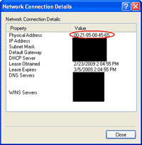
1. Before start, I’ll show the current MAC Address. It is 0021.8508.4565.
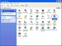
2. Open Control Panel. Click Start -> Settings -> Control Panel.
3. Open Network Connection Properties. Right-click on the network connection that you want to change MAC Address and select Properties.
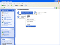
4. On the Connection Properties, click Configure.

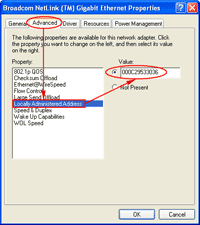
5. On Network Connection Properties, select Advanced tab -> select Locally Administrated Address or Network Address -> enter the MAC Address value that you want in the value box (without dot(.) or dash(-) between the MAC Address numbers). In this example, I’ll set to “000C29530036″. Then, click OK.
Note: If you can’t find Locally Administrated Address or Network Address property, it means that the NIC doesn’t support virtual MAC Address feature so you can’t change MAC Address by this method.
6. The network connection will be restarted.
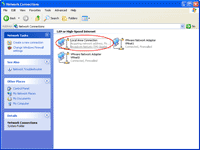
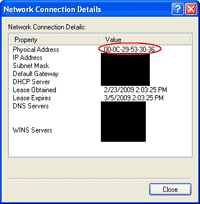
7. After that, observe the MAC Address of the network connection again. You’ll see that the MAC Address value has been changed to the value that I’ve just entered (00-0C-29-53-00-36).
8. To change the MAC Address value back to the original (the built-in value), just select Not Present or Use Default or delete out the configured MAC Address value on step 5 depends on which NIC you’re using.
Change MAC Address in Windows, Part III: Windows Registry
This post shows how to change MAC Address in Windows by edit Windows Registry. Before you read this post, I suggest you to read Change MAC Address in Windows, Part I: Introduction first. Also, if you haven’t try to change MAC Address by using feature on a NIC, I recommend to try it before on Part II: Feature on NIC.
If you have tried the first method and not succeed, it’s time to use this method to change MAC Address by modify the Windows Registry. It is a best practice to backup the Windows Registry before modify it.
Note: Changing MAC Address in Windows by this method is not supported by Microsoft. I’ll not be responsible on any damage or loss on your system. Do on your own risk!
Step-by-step:
1. Before start, I’ll show the current MAC Address. It is 00-21-85-08-45-65.

2. Open command prompt by click Start -> Run -> type “cmd” -> Press Enter. Then, type command below to list all NICs on the current computer.
net config rdr
In this example, there are 3 NICs (on red mark). The NIC that I want to change MAC Address is the first one which I have observed by the MAC Address at the end of each line. Then, I have to note down the string in the bracket {}, the easiest way is to copy and paste to the Notepad. In this example, I have noted the string {F2B0CA68-D2F5-4907-938E-DD338B60A8A0}.

3. Next, open Registry Editor by type the command below:
regedt32
Note: You can also use “regedit.exe”. For more information about these tools, read Differences between Regedit.exe and Regedt32.exe on Microsoft KB.
4. On Registry Editor, navigate to HKEY_LOCAL_MACHINE -> SYSTEM -> CurrentControlSet -> Control -> Class ->{4D36E972-E325-11CE-BFC1-08002bE10318}.
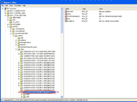
5. You see lots of sub-folders in {4D36E972-E325-11CE-BFC1-08002bE10318} with 00xx format, for instance 0001,0002,0003, etc. Now I have to compare the value of NetCfgInstanceId on each of these sub-folders with the value that I have noted down on step 2. In this example, I have found the match on 0001 sub-folder. Normally, you should find the match on 0000 sub-folder.

6. Next, check if the key “NetworkAddress” is existed on the sub-folder in step 5 or not. If not, create a new key by right-click on the sub-folder -> New -> String Value. If there is already the key, goes to step 8.

7. Set name as “NetworkAddress”.

8. Double-click on the key NetworkAddress and assign MAC Addresss as you desire. In this example, I set to 0021850845AA.
Note: Enter the MAC Address without dash (-), dot (.), semi-colon (:).

9. The configuration will look similar to the figure below.

10. Open Network Connection by Start -> Settings -> Control Panel -> Network Connections. Disable the Network Connection by right-click and select Disabled.
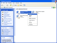
11. Enable the Network Connection by right-click and select Enabled.
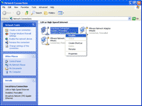
12. Observe the Network Connection again. Now the MAC Address has been changed to 00-21-85-08-45-AA.
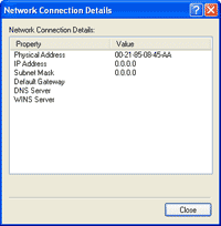
13. To change the MAC Address value back to the original (the built-in value), simply remove out the value that you have set on step 8 and restart the network connection again.
http://www.linglom.com/2009/04/26/change-mac-address-in-windows-part-iii-windows-registry/
Sunday, September 20, 2009
Subnetting - What, When and How
Subnetting is essentially the modification of a single IP network to create two or more logically visible sub-sections. It entails changing the subnet mask of the local network number to produce an even number of smaller network numbers, each with a corresponding range of IP addresses.
When is subnetting necessary?
Subnetting is required when one network number needs to be distributed across multiple LAN segments. This may be the case in instances when:
* A company uses two or more types of LAN technology (for example, Ethernet, Token Ring) on their network.
* Two network segments are restricted by distance limitations (for example, remote offices linked via point-to-point circuit).
* Segments need to be localized for network management reasons (accounting segment, sales segment, etc.).
* Hosts which dominate most of the LAN bandwidth need to be isolated.
Advantages and Disadvantages:
Hopefully your decision to subnet happened before your workstations were assigned IP addresses. This will allow for much more flexibility in your segment layout. Subnetting can provide you with easier network management capabilities and also lends itself to faster troubleshooting. Additionally, subnetting keeps the size of the Internet's routing tables down, since you won't be adding an additional network number for each segment.
The routing announcement of your network to the outside world will still be based on your single network number. Keep in mind, though, that subnetting will decrease the total amount of IP addresses available to you and may require purchasing additional hardware such as a router. This will be covered later.
How It Works:
An IP address is a 32 bit number divided into 4 sections of 8 bits called octets. Each octet is usually converted from binary to decimal form and separated with a dot to make it readable. The address can also be split into a network and host portion.
The network portion always remains fixed for a particular network, while the remaining bits which make up the host portion can be altered to give the range of addresses to assign to hosts.
In order to determine where the network portion ends and the host portion begins, a subnet mask (or netmask, or just mask) is used to fix the network portion and allow the host portion to be changed. As an example, we will use the IP number 38.9.211.0 with a subnet mask of 255.255.255.0. Changing to binary, we get:

A binary 1 will "mask" the bit, and a 0 will deem it variable. So, for this case, we refer to the netmask as 24 bits, or /24
.38.9.211.0/24
The fixed bits become the network portion and the remaining bits become the host portion, so in this case there are 8 host bits which account for a range from 0-255. IP protocol standards dictate that we use addresses of all 0's to refer to the network as a whole, and addresses of all 1's to refer to the broadcast of all hosts on the network, so these host addresses may not be used. This limits our host range from 1 - 254.
| 38.9.211.0/24 | the entire /24 network |
| 38.9.211.1 - 38.9.211.254 | range of valid hosts |
| 38.9.211.255 | broadcast address of all hosts on the network |
Once you receive your network number, whether it's a /24, /25, or /27, you have the ability to extend the network portion further into the host-number field by lengthening the netmask. The number of bits that you extend into the original host portion determines how many segments, or subnets, you will produce.
To be specific, lengthening the mask by n bits will produce 2^n subnets.
Let's illustrate what would happen if we used 2 subnet bits. The host portion would be reduced to six bits. There are 4 different combinations of arranging the 2 subnet bits, so we arrive at 4 unique subnets.
| Subnet 1 | 00000000 - 00111111 | (.0 - .63) |
| Subnet 2 | 01000000 - 01111111 | (.64 - .127) |
| Subnet 3 | 10000000 - 10111111 | (.128 - .191) |
| Subnet 4 | 11000000 - 11111111 | (.192 - .255) |
What we have accomplished is creating 4 network numbers from 1. Once again, adhering to our rule that all 0's is a network, and all 1's is a broadcast, we can see where each subnetwork begins and ends.
| Network | Host Ranges | Broadcast |
| 38.9.211.0/26 ** | 38.9.211.1 - 38.9.211.62 | 38.9.211.63 |
| 38.9.211.64/26 | 38.9.211.65 - 38.9.211.126 | 38.9.211.127 |
| 38.9.211.128/26 | 38.9.211.129 - 38.9.211.190 | 38.9.211.191 |
| 38.9.211.192/26 ** | 38.9.211.193 - 38.9.211.254 | 38.9.211.255 |
**An Important Note
Some older routers do not send subnet masks for every announced route. These routers do not understand the all 0's and all 1's subnets, so they may not be used. However, if you are using an assigned number from our net 38 block (for example, 38.x.x.x), or if your router allows you to provide netmasks in its routing table, these subnets are routable.
http://www.support.psi.com/support/common/routers/files/SUBNET-Desc.html
Sample Subnetting Topology

The figure above illustrates a topology which can route the same network number over 3 segments, one of which is linked across a PPP connection. The /24 network was split into 4 subnets (since you may only produce 2^n subnets) using a /26 mask.
Configuration:
Each router and workstation will use a 255.255.255.192 subnet mask in its IP configuration. The default gateway will always be the IP address of the closest router to the Internet on the segment.
TCP/IP Config .
Subnet 3 - 38.9.211.128/26
The following use 38.9.211.129 as a default gateway:
38.9.211.130
28.9.211.131
38.9.211.132
Subnet 2 - 38.9.211.64/26
The following use 38.9.211.65 as a default gateway:
38.9.211.69
38.9.211.68
38.9.211.67
38.9.211.66
Subnet 1 - 38.9.211.0/26
The following use 38.9.211.1 as a default gateway:
38.9.211.5
38.9.211.4
38.9.211.3
38.9.211.2
Static vs. Dynamic Routing:
Internal routing may be accomplished statically or dynamically. For dynamic routing, an internal protocol such as rip may be used. Each router will create its own routing table based on rip announcements. If static routing is preferred, the tables will need to be created manually. The table below illustrates what the routing table will look like on each router. The default gateway is identified by the 0.0.0.0 route which refers to any route that is not explicitly matched in the routing table.
Router 4 (38.9.211.129)
0.0.0.0 via PPP WAN link
Router 3 (38.9.211.69)
0.0.0.0 via 38.9.211.65
38.9.211.128 255.255.255.192 via PPP WAN link
Router 2 (38.9.211.5)
0.0.0.0 via 38.9.211.1
38.9.211.128 255.255.255.192 via 38.9.211.69
38.9.211.64 255.255.255.192 via 38.9.211.65
Router 1 (38.9.211.1)
0.0.0.0 via WAN link or PSINet POP IP address
38.9.211.128 255.255.255.192 via 38.9.211.5
38.9.211.64 255.255.255.192 via 38.9.211.5
38.9.211.0 255.255.255.0 via 38.9.211.1 (Full /24 announcement)
Getting started with Microsoft ISA Server 2006, Part I: Installation
Microsoft Internet Security & Acceleration Server 2006 is a firewall and proxy product from Microsoft. It can protects local network from hackers, limit access for internet access, improve internet speed for users and also logging any connections that pass through ISA Server.
Or you can say that ISA Server is a gateway between intranet(LAN) and internet so it has more than one network interfaces usually it has 2 or 3 network interfaces depends on network topology(Edge firewall, 3-Leg Perimeter, etc.) in your organization.
The series are divided into 5 parts:
* Getting started with Microsoft ISA Server 2006, Part I: Installation
* Getting started with Microsoft ISA Server 2006, Part II: Configure Network Topology
* Getting started with Microsoft ISA Server 2006, Part III: Create Firewall Policy Rule
* Getting started with Microsoft ISA Server 2006, Part IV: Configure Client Type
* Getting started with Microsoft ISA Server 2006, Part V: Configure HTTP Filter
This post will show how to install ISA Server 2006 Standard Edition on a Windows 2003 Server which has 2 network interfaces: one is connected to internal network(LAN) and the other connected to external(Internet). The diagram is as below:

Step-by-step:
1. Open ISA setup program.

2. Click Next.


4. Select Setup Type. If you want to customize features or change installed directory, select Custom. Otherwise, select Typical. I leave Typical for convenience.

5. On Internal Network, you must enter your internal IP address range. You can do this by adding manually or select from network adapter. Before click Next, ensure that your network addressed was configured correctly.

6. On Firewall Client Connections, if you haven’t upgrade from previous ISA Server(ISA 2000 or 2004), leave the check box uncheck and click Next. Otherwise, check the check box before continue.

7. On Service Warning, click Next. Notice that some of services will be restarted or disabled while installing.

8. Click Install.

9. Wait for install finishes.

10. You can check “Invoke ISA Server Management when the wizard closes” if you want to configure ISA now.

11. Now you have finished installing ISA Server 2006. For configure the ISA details, continue on the next part.

Saturday, September 19, 2009
Getting started with Microsoft ISA Server 2006, Part II: Configure Network Topology
From Part I, you have finished install ISA Server 2006. Before using the server, you need to do some configurations first. On Getting Started with ISA Server 2006 page on ISA Server Management, there are 5 steps for set up ISA Server as the figure below.

To use ISA Server, only first 2 steps on the figure above are needed to be configured so this part will shows how to configure Network Topology on ISA Server which is the first step in the figure above. For the second step, I will cover in the next part(part III). Also, you need to enable client to access ISA Server by configure on clients,too. Client Configuration will be covered in part IV.
ISA Server 2006 comes with many defined templates. Here are some details of each template. You can select one of them that match your network.
1. Edge Firewall:
This is a standard network topology for small to medium organization. The ISA Server is a main gateway controlling traffic between intranet and internet. The ISA Server needs 2 network interfaces

2. 3-Leg Perimeter:
This is a standard network topology for medium to large organization. There are another network which is Perimeter network adding to ISA server compare to edge firewall. The perimeter network or DMZ (Demilitarized Zone) is a network that is less secure for serving Web server, E-Mail server, DNS server,etc so that internet users can access these services without access to internal network. The ISA Server needs 3 network interfaces.

3. Front Firewall:
This is a network topology for organization that security is high priority. In this case, there are more than 1 firewall server. When hacker attacks the server and one fails, there is still back firewall to protect your internal network. This template, ISA Server will be act as front firewall server between internet and perimeter network and needs 2 network interfaces.

4. Back Firewall:
This is a network topology for organization that security is high priority. The configuration is the same as in Front Firewall template except that the ISA Server that you’re configuring is the back firewall that serperate internal and perimeter network.This template, ISA Server needs 2 network interfaces.

5. Back Firewall:
This is a network topology for organization that security is high priority. The configuration is the same as in Front Firewall template except that the ISA Server that you’re configuring is the back firewall that serperate internal and perimeter network.This template, ISA Server needs 2 network interfaces.

Note: For Front and Back Firewall templates, you have more than one firewall servers. It is best practice that you should use different firewall software or using hardware firewall with software firewall not the same on front and back. If hacker can destroy the front firewall, you still have back firewall which the hacker can’t use the previous technique to attack the firewall.
Step-by-step:
This example will configure ISA Server 2006 using Edge Firewall template.
1. Open ISA Server Management.
1. On left window, expand Configuration and select Networks
2. On right window, select Templates tab.
3. Click on Edge Firewall template. Network Template Wizard window appears.

* Click Next.

* You can export your configurations before let the wizard overwrite the old one by click on Export button. Otherwise, click Next.

* On Internal Network IP Addresses, you can configure your internel network IP Address. If the existing value is correct, click Next.

* On Select a Firewall Policy, you can select firewall policy template. The description will display what will be configure on ISA Server. I select “Block all” to block all traffic between ISA Server. I will configure rules later in the the next part.

* Click Finish to complete the wizard.

* To make ISA Server takes effect, click on Apply.

Getting started with Microsoft ISA Server 2006, Part III: Create Firewall Policy Rule
From part II, you have configured Network Topology. Now you need to create a policy rule to allow traffic pass through the ISA Server.
By default, ISA Server is configured with default rule which blocks all traffics pass through ISA Server. But you can customize rules to match your policy in organization. On each rule, you can customize to allow or deny access, protocols, source and destination addresses, users (ISA Server can integrated with Active Directory), time to use the rule, content types.
Step-by-step:
Next, I will create a new web access rule for all users in internal network to access internet(external network) with only HTTP (port 80) and HTTPS (port 443) protocols.
1. Open ISA Server Management. Expand server name(in this example, BKKFRW001) -> Right click on Firewall Policy -> New -> Access Rule.

2. New Access Rule Wizard appears, enter the name of access rule. Click Next.

3. On Rule Action, select Allow. Click Next.

4. On Protocols, click Add. Add Protocols window appears, expand Common protocols and select HTTP and HTTPS.

5. On Access Rule Sources, click Add. Add Network Entities window appears, expand Networks and select Internal.

6. On Access Rule Sources, click Add. Add Network Entities window appears, expand Networks and select Internal.

7. On User Sets, leave All Users. Click Next.

8. Click Finish to complete create new rule.

9. Again, don’t forget to apply your setting on ISA Server to take effect. Click Apply.

10. Next part will be about client configuration to access to ISA Server.